Explore prime industrial inventory compliant with ASME, ANSI, JIS, DIN, and GB standards. Direct line components engineered for petroleum refining, marine engineering, and power utilities.
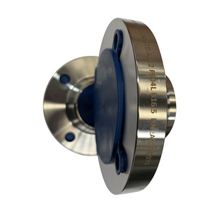
A rigorous review of structural load paths, double fillet welding procedures, and stress distribution thresholds according to ASME Section VIII Division 1 and ASME B31.3 piping codes.
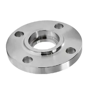
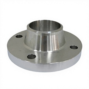
The Slip-On Flange (designated as SO flange) remains one of the most widely deployed connection components across medium-to-low pressure fluid infrastructure, hydrocarbon transportation, and chemical processing facilities. Structurally distinguished by an inner bore marginally larger than the outer diameter (OD) of the mating pipe, the pipe slips entirely through the hub or plate bore before being anchored by two distinct fillet welds: one external fillet weld situated at the hub shoulder and one internal seal weld applied close to the flange face.
Under mechanical stress, internal pressure vectors generate hoop stress and longitudinal bending moments across the flange hub. In contrast to the continuous butt-welded transition characteristic of weld neck (WN) flanges, the slip-on configuration transfers mechanical shear stress directly into the fillet weld throat geometry. Calculated stress concentrations under cyclic loading yield a fatigue life approximately one-third that of a corresponding butt-weld joint, making precise dimensional tolerance of the inner bore and rigorous fillet throat dimensioning paramount for process plant integrity.
To avoid thermal distortion or molten erosion of the raised face gasket surface during welding, ASME B31.3 stipulates an internal setback. The pipe must terminate approximately X = T + 1.5 mm (or 1/16 inch) back from the flange mating face, where T represents the nominal pipe wall thickness. Failure to maintain this setback risks localized pitting or gasket seating plane warping during the root pass.
Evaluating standard compliance metrics across ASME B16.5, ASME B16.47 Series A/B, and European EN 1092-1 Type 01 (plate) and Type 12 (hubbed slip-on) specifications.
| Material Designation | Standard Spec | Yield Strength (Min MPa) | Tensile Strength (MPa) | Operating Temperature Range | Primary Industrial Use Case |
|---|---|---|---|---|---|
| ASTM A105 | Carbon Steel Forged | 250 MPa | 485 MPa | -29°C to 425°C | Refining headers, non-corrosive steam, Class 150/300 utilities |
| ASTM A350 LF2 Class 1 | Low Temp Carbon Steel | 250 MPa | 485 - 655 MPa | -46°C to 345°C (Charpy V-notch @ -46°C) | Cryogenic processing, arctic gas pipelines, subsea manifolds |
| ASTM A182 F304 / F304L | Austenitic Stainless | 205 / 170 MPa | 515 / 485 MPa | -196°C to 538°C | Food processing, petrochemicals, general corrosive chemicals |
| ASTM A182 F316 / F316L | Molybdenum Stainless | 205 / 170 MPa | 515 / 485 MPa | -196°C to 650°C | Desalination brine lines, marine engineering, acid transport |
| ASTM A182 F51 (Duplex 2205) | Austenitic-Ferritic Duplex | 450 MPa | 655 - 880 MPa | -50°C to 300°C (PREN ≥ 35) | Offshore platform piping, high chloride & sour gas service |
| ASTM A182 F11 / F22 | Chrome-Moly Alloy | 205 / 310 MPa | 415 / 515 MPa | Up to 593°C | Thermal power plants, high-pressure superheated steam coils |
ASME B16.5 prescribes raised face (RF) serration profiles within 125 to 250 microinches (Ra 3.2 to 6.3 μm) Ra arithmetic average roughness. Chinese precision CNC machining employs phonographic spiral or concentric serration grooves (45 to 55 grooves per inch) to guarantee complete gasket flow bite under bolt compression.
Inner bore diameter tolerances for slip on flanges are strictly controlled. Under 10 inches, tolerance is held within +0.8 mm / -0.0 mm (+0.03 in / -0.00 in). Over 12 inches, radial tolerance remains +1.5 mm / -0.0 mm. Tight radial clearance prevents eccentricity and pipe misalignment during internal welding.
For high-pressure slip-on configurations (Class 600 through Class 1500), RTJ metallic octagonal ring grooves (ASME B16.20) are precision cut to surface finishes under Ra 1.6 μm, with flank angles calibrated strictly at 23° (±0.5°) to avoid fluid bypassing under vibration.
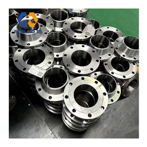
Combining heavy-tonnage hydraulic forging hammers, automated continuous heat-treatment furnaces, and ISO 17025 accredited metallurgical verification laboratories.
Every single slip on flange produced is hot-stamped with a unique heat code, material grade, schedule, and dimensional rating. This directly ties back to EN 10204 3.1 Mill Test Certificates (MTC), documenting complete ladle melt chemical breakdown and tensile/impact verification.
Our collaborative manufacturing nodes are accredited under ISO 9001, Indian Boiler Regulations (IBR), Engineers India Limited (EIL), and the Pressure Equipment Directive (PED 2014/68/EU), qualifying components for direct use in ADNOC, Aramco, and Shell EPC contractor bid sheets.
Equipped with 11 specialized testing stations: Oxford Instruments optical emission spectrometers (OES), automated ultrasonic flaw detectors (UT), magnetic particle inspection (MPI) rigs, digital Brinell/Vickers hardness testers, and cryogenic Charpy impact testing troughs down to -196°C.
For large diameter slip on flanges extending up to 60 inches (ASME B16.47 Series A & B), our advanced German Wagner ring-rolling machines align metal grain structures seamlessly along the circumferential perimeter, yielding unmatched burst-pressure safety margins over segmented plate cuts.
Exporting to over 45 destination ports throughout North America, the European Union, UAE, Saudi Arabia, Malaysia, and Singapore. Packaging conforms to ISPM-15 treated fumigated timber boxes with rust-inhibitive VCI (Volatile Corrosion Inhibitor) heat-sealed barrier films.
Strategic transformations reshaping Chinese forging ecosystems: green metallurgy, automation, ESG tracking, and procurement risk hedging.
As EPC enterprises and procurement officers navigate shifting macroeconomic horizons, the global purchasing criteria for slip on flanges are rapidly transcending base per-kilogram pricing. The forward-looking Chinese forging ecosystem is undergoing four monumental strategic pivots:
In-depth technical clarifications addressing standard interpretations, inspection protocols, and material selection criteria.
Slip-on flanges are preferred when initial fabrication cost, field alignment simplicity, and limited space are overriding considerations. Because the pipe slips directly into the flange bore, pipe ends require simple square cutting without expensive beveling preparation. However, slip-on flanges are generally restricted to ASME Class 150, 300, and 600 systems. Weld Neck flanges should be prioritized in severe cyclic service, operating temperatures above 400°C, severe hydrogen embrittlement environments, or where 100% radiographic examination (RT) of full-penetration butt welds is contractually mandated by plant design specs.
ASME B31.3 Process Piping Code mandates that slip-on flanges be joined using two separate fillet welds: an exterior fillet weld located at the back hub and an internal fillet weld executed at the intersection of the inner bore and the pipe cut end. The exterior weld provides structural strength against external bending, moment arm forces, and pipeline vibration. The interior weld seals against internal fluid pressure, prevents crevice corrosion in the annular space between pipe OD and flange ID, and prevents the corrosive medium from contacting the non-welded contact line.
Visual and dimensional inspection alone cannot detect internal metallurgical flaws like hydrogen flakes, cooling micro-fissures, or segregation voids. Qualified Chinese forging factories implement comprehensive Non-Destructive Examination (NDE):
During incoming document review, engineers should look for: (1) Missing Ladle Carbon Equivalent (CE) calculations for A105 steel (CE = C + Mn/6 + (Cr+Mo+V)/5 + (Ni+Cu)/15 must not exceed 0.45% for weldability); (2) Missing Charpy V-notch impact energy absorption figures and test temperatures for ASTM A350 LF2; (3) Positive Material Identification (PMI) chemical assay showing Chromium < 16.0% or Nickel < 10.0% for 316 stainless; (4) Vague heat treatment declarations lacking specific holding temperature, quench media, or soaking duration.
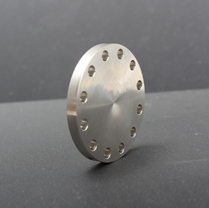
No. Slip-on flanges possess a hollow cylindrical hub bore intended strictly for pipe insertion. Modifying an SO flange by welding a flat blank plate into the center creates unverified stress concentrations not recognized under ASME B16.5, voiding pressure ratings. Orifice metering flanges require specialized radial differential pressure tapping ports (ASME B16.36) and precision-drilled pressure passages that require thick-walled weld-neck forgings to accommodate the extraction taps without violating minimum wall thickness requirements.
Direct mill pricing, full EN 10204 3.1 certification, third-party inspection compliance (SGS, BV, TÜV), and guaranteed dimensional precision for your international piping contracts.
Get Catalog