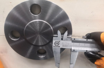
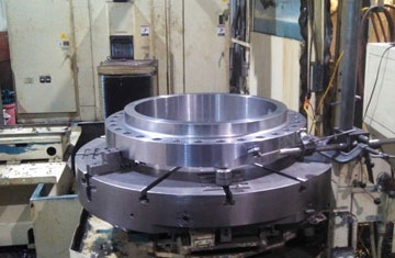
Type 05 Blank (Blind) Flange
Solid forged disc without a central bore, engineered to safely isolate piping lines, pressure vessel nozzles, and inspectable headers.

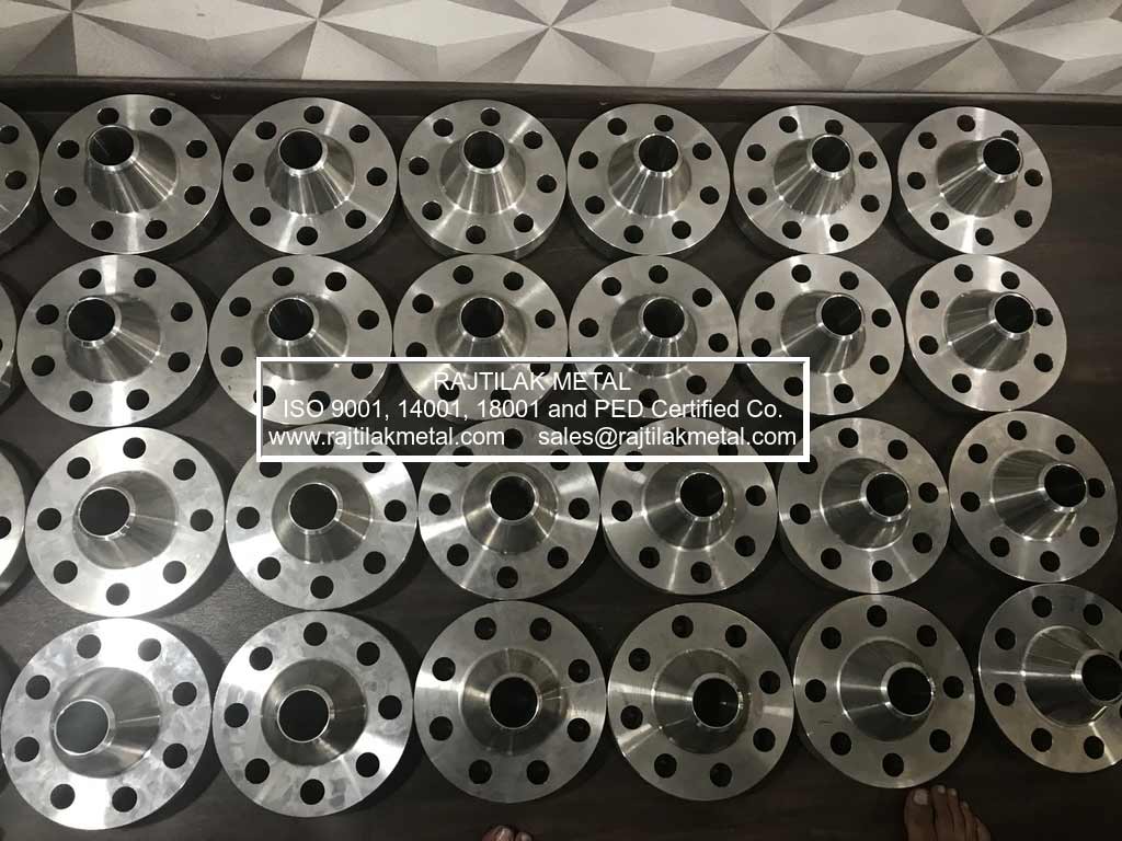
EN 1092-1 is the harmonized European standard for circular steel flanges, superseding legacy national DIN standards (including DIN 2501, 2632, and 2633). As an ISO 9001, EIL, and IBR approved manufacturer based in Mumbai, India, Rajtilak Metal produces fully certified European standard flanges engineered for oil & gas, chemical processing, maritime pipelines, and high-pressure steam utility circuits.
The standard establishes pressure-temperature ratings, dimensions, dimensional tolerances, threading configurations, bolt patterns, and strict material verification under EN 10204 3.1 certification. Flanges are manufactured using controlled hot forging, solution annealing, and CNC machining processes.
Standardized mechanical designs adapted for specific structural rigidity, pressure holding capability, and fabrication methods across industrial piping circuits.
Solid forged disc without a central bore, engineered to safely isolate piping lines, pressure vessel nozzles, and inspectable headers.
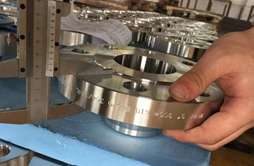
Engineered with a tapered hub transition to reduce stress concentration, ideal for cyclic fatigue, severe thermal loads, and extreme pressures.
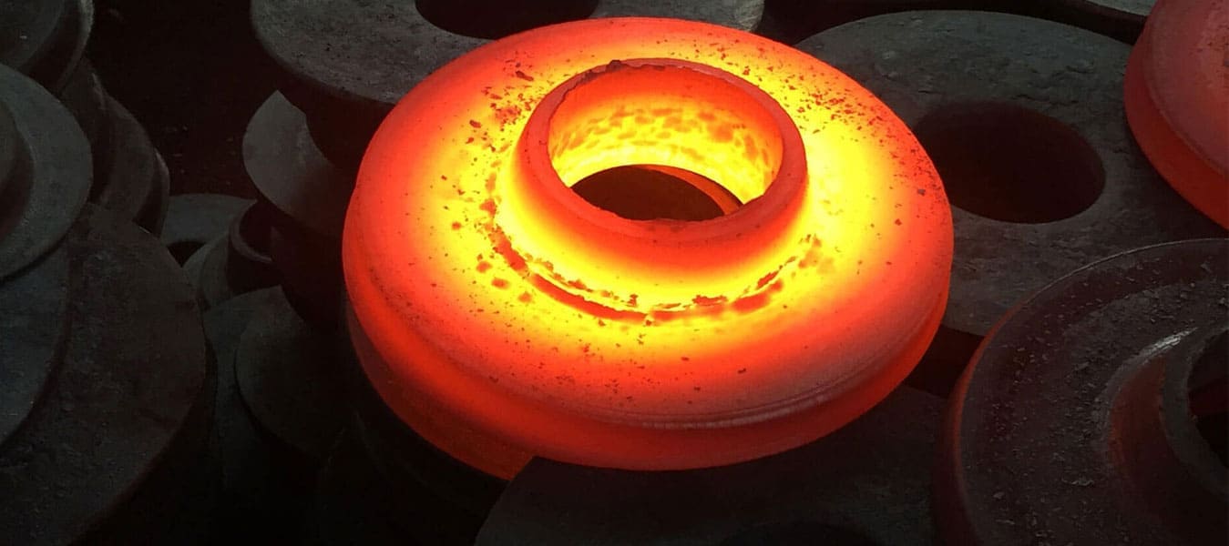
Flat circular plate flange slip-fitted over pipe outer diameters and secured with fillet welds for low to medium pressure utility services.
Type 12 hubbed slip-on and Type 13 hubbed threaded flanges for reliable mechanical joints without on-site welding constraints.
Comprehensive standard overview covering manufacturing limits, material grades, testing protocols, and certified testing options.
| Parameter | Standard Engineering Scope |
|---|---|
| Governing Standards | EN 1092-1 (Steel Flanges), EN 1092-2 (Cast Iron Flanges), DIN EN 1092-1, ISO 7005-1 |
| Nominal Diameters | DN 10 to DN 4000 (Metric European nominal bore sizing) |
| Nominal Pressure (PN) | PN 2.5, PN 6, PN 10, PN 16, PN 25, PN 40, PN 63, PN 100, PN 160, PN 250, PN 320, PN 400 |
| Flange Facing Options | Type A (Flat Face), Type B (Raised Face B1/B2), Type C (Tongue), Type D (Groove), Type E (Spigot), Type F (Recess), Type G/H (O-Ring) |
| Carbon Steel Grades | P235GH, P245GH, P250GH, P265GH, P280GH, S235JR, ASTM A105, C22.8 |
| Stainless Steel Grades | 1.4301 (304), 1.4307 (304L), 1.4401 (316), 1.4404 (316L), 1.4541 (321), 1.4571 (316Ti), 1.4539 (904L) |
| Alloy & Duplex Grades | 1.4462 (Duplex 2205), 1.4410 (Super Duplex 2507), 16Mo3, 13CrMo4-5, 10CrMo9-10, Inconel, Hastelloy, Monel |
| Testing & Inspection | Hydrostatic pressure test, Ultrasonic (UT), Magnetic Particle (MPI), Dye Penetrant (DPI), PMI chemical verification |
| Quality Certification | EN 10204 Type 3.1 MTC with full heat traceability, third-party inspection (TUV, DNV, BV, Lloyds, SGS) |
Dimensional tables for Type 11 welding neck flanges across PN 10, PN 16, PN 25, and PN 40 pressure classes.
| DN | Pipe OD (d1) | Flange OD (D) | PCD (k) | Thickness (b) | Neck Hub (d3) | RF Dia (d4) | Hole Dia (d2) | Bolts | Weight (Kg) |
|---|---|---|---|---|---|---|---|---|---|
| 200 | 219.1 | 340 | 295 | 24 | 234 | 268 | 22 | 8 × M20 | 11.60 |
| 250 | 273.0 | 395 | 350 | 26 | 292 | 320 | 22 | 12 × M20 | 15.80 |
| 300 | 323.9 | 445 | 400 | 26 | 342 | 370 | 22 | 12 × M20 | 18.30 |
| 350 | 355.6 | 505 | 460 | 26 | 385 | 430 | 22 | 16 × M20 | 25.30 |
| 400 | 406.4 | 565 | 515 | 26 | 440 | 482 | 26 | 16 × M24 | 30.60 |
| 450 | 457.0 | 615 | 565 | 28 | 488 | 532 | 26 | 20 × M24 | 35.10 |
| 500 | 508.0 | 670 | 620 | 28 | 542 | 585 | 26 | 20 × M24 | 40.50 |
| 600 | 610.0 | 780 | 725 | 30 | 642 | 685 | 30 | 20 × M27 | 52.90 |
| 800 | 813.0 | 1015 | 950 | 38 | 850 | 905 | 33 | 24 × M30 | 102.00 |
| 1000 | 1016.0 | 1230 | 1160 | 44 | 1052 | 1110 | 36 | 28 × M33 | 161.00 |
| 1200 | 1219.0 | 1455 | 1380 | 55 | 1256 | 1330 | 39 | 32 × M36 | 258.00 |
| DN | Pipe OD (d1) | Flange OD (D) | PCD (k) | Thickness (b) | Neck Hub (d3) | RF Dia (d4) | Hole Dia (d2) | Bolts | Weight (Kg) |
|---|---|---|---|---|---|---|---|---|---|
| 15 | 21.3 | 95 | 65 | 16 | 32 | 45 | 14 | 4 × M12 | 0.68 |
| 25 | 33.7 | 115 | 85 | 18 | 46 | 68 | 14 | 4 × M12 | 1.09 |
| 50 | 60.3 | 165 | 125 | 18 | 74 | 102 | 18 | 4 × M16 | 2.53 |
| 80 | 88.9 | 200 | 160 | 20 | 105 | 138 | 18 | 8 × M16 | 3.92 |
| 100 | 114.3 | 220 | 180 | 20 | 131 | 158 | 18 | 8 × M16 | 4.62 |
| 150 | 168.3 | 285 | 240 | 22 | 184 | 212 | 22 | 8 × M20 | 7.81 |
| 200 | 219.1 | 340 | 295 | 24 | 235 | 268 | 22 | 12 × M20 | 11.50 |
| 250 | 273.0 | 405 | 355 | 26 | 292 | 320 | 26 | 12 × M24 | 16.70 |
| 300 | 323.9 | 460 | 410 | 28 | 344 | 378 | 26 | 12 × M24 | 22.10 |
| 400 | 406.4 | 580 | 525 | 32 | 445 | 490 | 30 | 16 × M27 | 41.10 |
| 600 | 610.0 | 840 | 770 | 40 | 670 | 725 | 36 | 20 × M33 | 96.00 |
| DN | Pipe OD (d1) | Flange OD (D) | PCD (k) | Thickness (b) | Neck Hub (d3) | RF Dia (d4) | Hole Dia (d2) | Bolts | Weight (Kg) |
|---|---|---|---|---|---|---|---|---|---|
| 15 | 21.3 | 95 | 65 | 16 | 32 | 45 | 14 | 4 × M12 | 0.77 |
| 25 | 33.7 | 115 | 85 | 18 | 46 | 68 | 14 | 4 × M12 | 1.30 |
| 50 | 60.3 | 165 | 125 | 20 | 75 | 102 | 18 | 4 × M16 | 2.85 |
| 80 | 88.9 | 200 | 160 | 24 | 105 | 138 | 18 | 8 × M16 | 4.78 |
| 100 | 114.3 | 235 | 190 | 24 | 134 | 162 | 22 | 8 × M20 | 6.46 |
| 150 | 168.3 | 300 | 250 | 28 | 192 | 218 | 26 | 8 × M24 | 11.70 |
| 200 | 219.1 | 375 | 320 | 34 | 244 | 285 | 30 | 12 × M27 | 21.00 |
| 250 | 273.0 | 450 | 385 | 38 | 306 | 345 | 33 | 12 × M30 | 34.20 |
| 300 | 323.9 | 515 | 450 | 42 | 362 | 410 | 33 | 16 × M30 | 47.60 |
| 400 | 406.4 | 660 | 585 | 50 | 462 | 535 | 39 | 16 × M36 | 98.00 |
Standard dimensions and nominal weights for flat slip-on plate flanges and solid blind flange closures.
| DN | Pipe OD | Flange Bore (d1) | OD (D) | PCD (k) | Thickness (b) | Hole Dia (d2) | Bolt Holes | Weight (Kg) |
|---|---|---|---|---|---|---|---|---|
| 15 | 21.3 | 22.0 | 95 | 65 | 14 | 14 | 4 × M12 | 0.67 |
| 25 | 33.7 | 34.5 | 115 | 85 | 16 | 14 | 4 × M12 | 1.11 |
| 50 | 60.3 | 61.5 | 165 | 125 | 20 | 18 | 4 × M16 | 2.72 |
| 80 | 88.9 | 90.5 | 200 | 160 | 20 | 18 | 8 × M16 | 3.59 |
| 100 | 114.3 | 116.0 | 220 | 180 | 22 | 18 | 8 × M16 | 4.38 |
| 150 | 168.3 | 170.5 | 285 | 240 | 24 | 22 | 8 × M20 | 7.12 |
| 200 | 219.1 | 221.5 | 340 | 295 | 26 | 22 | 12 × M20 | 9.71 |
| 250 | 273.0 | 276.5 | 405 | 355 | 29 | 26 | 12 × M24 | 14.16 |
| 300 | 323.9 | 327.5 | 460 | 410 | 32 | 26 | 12 × M24 | 18.93 |
| 400 | 406.4 | 411.0 | 580 | 525 | 38 | 30 | 16 × M27 | 35.75 |
| 500 | 508.0 | 513.5 | 715 | 650 | 46 | 33 | 20 × M30 | 63.83 |
| DN | Outer Diameter (D) | PCD (k) | Thickness (b) | Hole Dia (d2) | Bolt Thread | Holes | Weight (Kg) |
|---|---|---|---|---|---|---|---|
| 15 | 95 | 65 | 16 | 14 | M12 | 4 | 0.81 |
| 25 | 115 | 85 | 18 | 14 | M12 | 4 | 1.38 |
| 50 | 165 | 125 | 18 | 18 | M16 | 4 | 2.88 |
| 80 | 200 | 160 | 20 | 18 | M16 | 8 | 4.61 |
| 100 | 220 | 180 | 20 | 18 | M16 | 8 | 5.65 |
| 150 | 285 | 240 | 22 | 22 | M20 | 8 | 10.50 |
| 200 | 340 | 295 | 24 | 22 | M20 | 12 | 16.20 |
| 250 | 405 | 355 | 26 | 26 | M24 | 12 | 25.00 |
| 300 | 460 | 410 | 28 | 26 | M24 | 12 | 35.10 |
| 400 | 580 | 525 | 32 | 30 | M27 | 16 | 63.50 |
| 500 | 715 | 650 | 44 | 33 | M30 | 20 | 133.00 |
Maximum allowable working pressures (in bar) categorized by operating temperature for standard carbon and structural steel flanges.
| Rating Class | -10°C to 200°C | 250°C | 300°C | 350°C | 400°C | 425°C | 450°C |
|---|---|---|---|---|---|---|---|
| PN 6 | 6.0 bar | 5.5 bar | 5.0 bar | — | — | — | — |
| PN 10 | 10.0 bar | 9.0 bar | 8.0 bar | 7.0 bar | 6.0 bar | — | — |
| PN 16 | 16.0 bar | 15.0 bar | 13.0 bar | 11.0 bar | 9.0 bar | — | — |
| PN 25 | 25.0 bar | 24.0 bar | 21.0 bar | 17.0 bar | 14.0 bar | 12.0 bar | 9.0 bar |
| PN 40 | 40.0 bar | 38.0 bar | 33.0 bar | 28.0 bar | 23.0 bar | 20.0 bar | 15.0 bar |
| PN 63 | 63.0 bar | 60.0 bar | 52.0 bar | 43.0 bar | 35.0 bar | 31.0 bar | 23.0 bar |
| PN 100 | 100.0 bar | 95.0 bar | 83.0 bar | 70.0 bar | 57.0 bar | 50.0 bar | 37.0 bar |
| PN 160 | 160.0 bar | 152.0 bar | 132.0 bar | 112.0 bar | 92.0 bar | 80.0 bar | 60.0 bar |