
European Standard PN Flanges (EN 1092-1 / DIN Specifications)
In metric industrial piping, the term PN designates Pression Nominale (Nominal Pressure rating in bar). Rajtilak Metal specializes in forging and precision machining metric flanges certified to DIN and EN 1092-1 specifications. Manufactured under strict ISO 9001 quality controls, each piece is stamped with the heat number and supplied with EN 10204 3.1 inspection documentation for global oil, gas, chemical, power, and water utility installations.
Nominal Pressure (PN)
Indicates maximum working pressure at 20°C in bar (e.g., PN16 = 16 bar rating). Operates smoothly under thermal and cyclic stress.
Global Accreditations
Fully compliant with EN 1092-1, DIN 2576, 2501, 2631-2635. Certified with IBR and third-party inspection agencies.
Comprehensive Grades
Stocked in carbon steel P235GH, P250GH, ASTM A105, stainless steel 304L/316L, duplex alloys, and nickel superalloys.
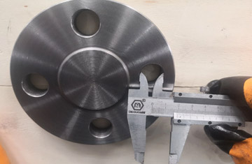
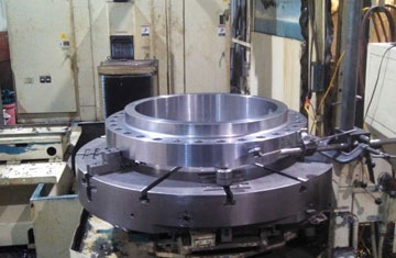
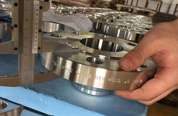
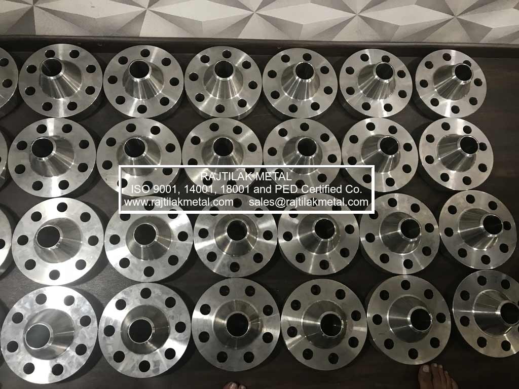
Comprehensive PN Flange Visual Classifications
We supply all standard flange designs across PN6 to PN100 ratings, tailored to metric tube dimensions and standard Schedule line executions.
Technical Specifications for PN Flanges
| Governing Standards | EN 1092-1, DIN 2501, DIN 2576, DIN 2527, DIN 2631, DIN 2632, DIN 2633, DIN 2634, DIN 2635, UNI 2278, BS 4504 |
|---|---|
| Nominal Pressure (PN) | PN 2.5, PN 6, PN 10, PN 16, PN 25, PN 40, PN 63, PN 100, PN 160 |
| Size Range | DN 10 to DN 2000 (3/8" to 80") |
| Flange Facings | Flat Face (Type A), Raised Face (Type B - RF), Tongue (Type C), Groove (Type D), Male (Type E), Female (Type F), O-ring Groove (Type H) |
| Material Grades | Carbon Steel (P235GH, P250GH, P265GH, P280GH, P355NH, A105) Stainless Steel (1.4301/304, 1.4307/304L, 1.4401/316, 1.4404/316L, 1.4541/321, 1.4571) Duplex & Super Duplex (1.4462 / 2205, 1.4410 / 2507) Alloy Steel (16Mo3, 13CrMo4-5, ASTM A182 F11, F22) |
| Quality Documentation | EN 10204 3.1 Mill Test Certificate, PMI Verification, 100% Dimensional & Visual Inspection, IBR Form III-C on demand |
DIN 2576 / EN 1092-1 Type 01 (Plate Slip-On) PN10 Dimensions
Plate slip-on flanges are primarily engineered for low-pressure utilities, industrial water routing, and chemical plant distribution systems.
| DN | Pipe O.D. (mm) | Flange O.D. (D) | Bore (d5) | Thickness (b) | Bolt Circle (k) | Bolt Holes | Bolt Size | Weight (kg) |
|---|---|---|---|---|---|---|---|---|
| DN 15 | 21.3 | 95 | 22.0 | 14 | 65 | 4 | M12 | 0.67 |
| DN 20 | 26.9 | 105 | 27.6 | 16 | 75 | 4 | M12 | 0.94 |
| DN 25 | 33.7 | 115 | 34.4 | 16 | 85 | 4 | M12 | 1.11 |
| DN 32 | 42.4 | 140 | 43.1 | 16 | 100 | 4 | M16 | 1.62 |
| DN 40 | 48.3 | 150 | 49.0 | 16 | 110 | 4 | M16 | 1.86 |
| DN 50 | 60.3 | 165 | 61.1 | 18 | 125 | 4 | M16 | 2.47 |
| DN 65 | 76.1 | 185 | 77.1 | 18 | 145 | 4 | M16 | 3.00 |
| DN 80 | 88.9 | 200 | 90.3 | 20 | 160 | 8 | M16 | 3.79 |
| DN 100 | 114.3 | 220 | 115.9 | 20 | 180 | 8 | M16 | 4.03 |
| DN 125 | 139.7 | 250 | 141.6 | 22 | 210 | 8 | M16 | 5.46 |
| DN 150 | 168.3 | 285 | 170.5 | 22 | 240 | 8 | M20 | 6.57 |
| DN 200 | 219.1 | 340 | 221.8 | 24 | 295 | 8 | M20 | 9.31 |
| DN 250 | 273.0 | 395 | 276.2 | 26 | 350 | 12 | M20 | 11.90 |
| DN 300 | 323.9 | 445 | 327.6 | 26 | 400 | 12 | M20 | 13.80 |
DIN 2633 / EN 1092-1 Type 11 (Welding Neck) PN16 Dimensions
Welding neck flanges are suitable for high structural reliability under severe vibrations, thermal expansion, and internal fluid pressure cycles.
| DN | Pipe O.D. (mm) | Flange O.D. (D) | Overall Height (h1) | Thickness (b) | Bolt Circle (k) | Bolt Holes | Bolt Size | Weight (kg) |
|---|---|---|---|---|---|---|---|---|
| DN 15 | 21.3 | 95 | 35 | 14 | 65 | 4 | M12 | 0.65 |
| DN 20 | 26.9 | 105 | 38 | 16 | 75 | 4 | M12 | 0.95 |
| DN 25 | 33.7 | 115 | 38 | 16 | 85 | 4 | M12 | 1.14 |
| DN 32 | 42.4 | 140 | 40 | 16 | 100 | 4 | M16 | 1.69 |
| DN 40 | 48.3 | 150 | 42 | 16 | 110 | 4 | M16 | 1.86 |
| DN 50 | 60.3 | 165 | 45 | 18 | 125 | 4 | M16 | 2.53 |
| DN 65 | 76.1 | 185 | 45 | 18 | 145 | 4 | M16 | 3.06 |
| DN 80 | 88.9 | 200 | 50 | 20 | 160 | 8 | M16 | 3.70 |
| DN 100 | 114.3 | 220 | 52 | 20 | 180 | 8 | M16 | 4.62 |
| DN 125 | 139.7 | 250 | 55 | 22 | 210 | 8 | M16 | 6.30 |
| DN 150 | 168.3 | 285 | 55 | 22 | 240 | 8 | M20 | 7.75 |
| DN 200 | 219.1 | 340 | 62 | 24 | 295 | 12 | M20 | 11.00 |
| DN 250 | 273.0 | 405 | 70 | 26 | 355 | 12 | M24 | 15.60 |
| DN 300 | 323.9 | 460 | 78 | 28 | 410 | 12 | M24 | 22.00 |
| DN 400 | 406.4 | 580 | 85 | 32 | 525 | 16 | M27 | 39.30 |
| DN 500 | 508.0 | 715 | 90 | 34 | 650 | 20 | M30 | 61.00 |
DIN 2527 / EN 1092-1 Type 05 (Blind Flange) Dimensions across PN Classes
Engineered to isolate process sections or terminate piping manifolds. Standard production features smooth or concentric serrated contact faces.
| DN | Pipe Size | PN6 O.D. (mm) | PN10 O.D. (mm) | PN16 O.D. (mm) | PN25 O.D. (mm) | PN40 O.D. (mm) |
|---|---|---|---|---|---|---|
| DN 15 | 1/2" | 80 | 95 | 95 | 95 | 95 |
| DN 20 | 3/4" | 90 | 105 | 105 | 105 | 105 |
| DN 25 | 1" | 100 | 115 | 115 | 115 | 115 |
| DN 32 | 1-1/4" | 120 | 140 | 140 | 140 | 140 |
| DN 40 | 1-1/2" | 130 | 150 | 150 | 150 | 150 |
| DN 50 | 2" | 140 | 165 | 165 | 165 | 165 |
| DN 65 | 2-1/2" | 160 | 185 | 185 | 185 | 185 |
| DN 80 | 3" | 190 | 200 | 200 | 200 | 200 |
| DN 100 | 4" | 210 | 220 | 220 | 235 | 235 |
| DN 125 | 5" | 240 | 250 | 250 | 270 | 270 |
| DN 150 | 6" | 265 | 285 | 285 | 300 | 300 |
| DN 200 | 8" | 320 | 340 | 340 | 360 | 375 |
| DN 250 | 10" | 375 | 395 | 405 | 425 | 450 |
| DN 300 | 12" | 440 | 445 | 460 | 485 | 515 |
Pressure-Temperature Rating Matrix (bar)
Maximum allowable working pressure (bar) for standard structural carbon steels (P245GH / P250GH) at designated operating temperatures (°C):
| Temperature (°C) | PN 6 | PN 10 | PN 16 | PN 25 | PN 40 | PN 63 | PN 100 |
|---|---|---|---|---|---|---|---|
| -10 to 50 | 6.0 | 10.0 | 16.0 | 25.0 | 40.0 | 63.0 | 100.0 |
| 100 | 5.3 | 8.8 | 14.1 | 22.1 | 35.3 | 55.6 | 88.3 |
| 150 | 4.8 | 8.0 | 12.8 | 20.0 | 32.0 | 50.4 | 80.0 |
| 200 | 4.3 | 7.2 | 11.5 | 18.0 | 28.8 | 45.4 | 72.0 |
| 250 | 3.9 | 6.4 | 10.3 | 16.1 | 25.8 | 40.6 | 64.5 |
| 300 | 3.4 | 5.7 | 9.1 | 14.3 | 22.8 | 36.0 | 57.1 |
| 350 | 3.0 | 5.0 | 8.0 | 12.5 | 20.0 | 31.5 | 50.0 |
| 400 | 2.6 | 4.3 | 6.9 | 10.8 | 17.3 | 27.2 | 43.2 |
PN16 Metric Bolting & Gasket Technical Data
| DN Size | Inches | Bolt Size x Length | Bolt Holes | PCD (mm) | Gasket I.D. (mm) | Gasket O.D. (mm) |
|---|---|---|---|---|---|---|
| DN 15 | 1/2" | M12 x 50 | 4 | 65 | 22 | 50 |
| DN 20 | 3/4" | M12 x 55 | 4 | 75 | 28 | 60 |
| DN 25 | 1" | M12 x 55 | 4 | 85 | 35 | 70 |
| DN 32 | 1-1/4" | M16 x 55 | 4 | 100 | 43 | 82 |
| DN 40 | 1-1/2" | M16 x 55 | 4 | 110 | 49 | 92 |
| DN 50 | 2" | M16 x 65 | 4 | 125 | 61 | 107 |
| DN 65 | 2-1/2" | M16 x 65 | 4 | 145 | 77 | 127 |
| DN 80 | 3" | M16 x 70 | 8 | 160 | 90 | 142 |
| DN 100 | 4" | M16 x 70 | 8 | 180 | 115 | 162 |
| DN 125 | 5" | M16 x 70 | 8 | 210 | 141 | 192 |
| DN 150 | 6" | M20 x 70 | 8 | 240 | 169 | 218 |
| DN 200 | 8" | M20 x 75 | 12 | 295 | 220 | 273 |
| DN 250 | 10" | M24 x 80 | 12 | 355 | 274 | 329 |
| DN 300 | 12" | M24 x 80 | 12 | 410 | 325 | 384 |