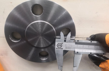
BS 10 Table D Flanges
Designed for low-pressure cooling water, municipal utilities, and light-duty steam systems. Rated for 100 psi (approx. 7 bar) at temperatures from -18°C to 230°C, with hydraulic test pressure at 150 psi.

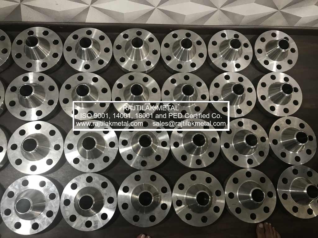
British Standard 10 (BS 10:1962) defines dimensions, bolt circles, nominal thickness, and pressure-temperature boundaries for flanges used in industrial piping, valves, pumps, and containment systems. Classified by lettered tables (Table D, Table E, Table F, Table H, Table J, Table K, Table R, Table S, Table T), the standard establishes reliable duty ratings from low-pressure utility lines up to 2800 psi severe hydraulic service.
All BS 10 flanges are supplied with EN 10204 3.1 inspection certification, full chemical and mechanical mill analysis, ultrasonic testing, and heat-number traceability stamped directly on the flange rim.
Understanding the dimensional differences, bolt counts, and working pressures among the primary BS 10 tables allows project engineers and procurement managers to ensure joint integrity across utility and process piping.
Designed for low-pressure cooling water, municipal utilities, and light-duty steam systems. Rated for 100 psi (approx. 7 bar) at temperatures from -18°C to 230°C, with hydraulic test pressure at 150 psi.
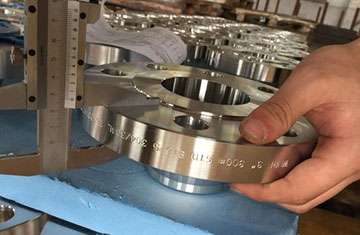
The most widely installed British Standard flange for process plants and commercial piping. Rated up to 200 psi (14 bar) at working temperatures up to 230°C, offering thicker profiles than Table D.
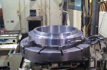
Heavy-duty flanges for medium-pressure steam, oil pipelines, and boiler lines. Rated for 300 psi (21 bar) working pressure up to 230°C, and hydraulic test pressure proofed to 450 psi.
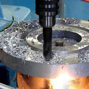
Engineered for high-pressure industrial service and power generation. Table H delivers 500 psi (35 bar) rating with 750 psi test, while Table J operates at 700 psi (48 bar) with a 1050 psi proof load.
Complete metallurgical and dimensional compliance for procurement engineers, EPC contractors, and global distribution partners.
| Parameter | Manufacturing Specification & Global Compliance Scope |
|---|---|
| Standard Specification | British Standard BS 10:1962 (Flanges and Bolting for Pipes, Valves, and Fittings) |
| Available Tables | Table A, Table D, Table E, Table F, Table H, Table J, Table K, Table R, Table S, Table T |
| Size Range | 1/2 inch (DN15) through 24 inch (DN600); larger diameters up to 48 inch manufactured to drawing |
| Flange Facings | Flat Face (FF), Raised Face (RF: 1/16″ or 1/4″), Ring Type Joint (RTJ), Tongue & Groove (T/G) |
| Facing Surface Finish | Stock Finish (Ra 3.2 to 6.3 μm / 125 to 250 μin), Smooth Finish (Ra 1.6 to 3.2 μm), Concentric / Spiral Serrated |
| Flange Types | Slip-On (SORF / SOFF), Weld Neck (WNRF), Blind (BLRF / BLFF), Screwed/Threaded (NPT/BSPT), Lap Joint, Plate Flanges |
| Carbon Steel Grades | ASTM A105, A105N, ASTM A350 LF2 (Low Temp), BS 1503-161, BS 1501-151, P235GH, P250GH |
| Stainless Steel Grades | ASTM A182 F304, F304L, F316, F316L, F321, F347, F310S, 904L, 1.4301, 1.4404 |
| Duplex & Alloy Grades | ASTM A182 F51 (UNS S31803 / 2205), F53 (UNS S32750 / 2507), F11, F22, F91, Monel 400, Inconel 625, Hastelloy C276 |
| Marking Format | Manufacturer's Brand, BS 10 Table designation, Nominal Size, Material Grade, Heat Number stamped on rim |
| Quality Certification | EN 10204 3.1 Mill Test Certificate, NDT (UT/MT/PT), PMI Spectroscopy, Hydrostatic Test Reports |
Nominal sizes from 1/2 inch to 24 inch. All dimensions comply with standard BS 10 Table D tolerance protocols.
| Nominal Bore (NPS) | DN (mm) | Flange OD (D) | PCD (K) | Hole Dia (L) | Flange Thk (C) | Raised Face (B) | Neck Dia (A) | No. of Bolts | Bolt Size (in) |
|---|---|---|---|---|---|---|---|---|---|
| 1/2″ | 15 | 95.3 | 66.8 | 14.5 | 4.8 | 22.4 | 21.3 | 4 | 1/2″ |
| 3/4″ | 20 | 101.6 | 73.2 | 14.5 | 4.8 | 27.7 | 26.7 | 4 | 1/2″ |
| 1″ | 25 | 114.3 | 82.6 | 14.5 | 4.8 | 34.6 | 33.5 | 4 | 1/2″ |
| 1-1/4″ | 32 | 120.7 | 87.4 | 14.5 | 6.4 | 43.2 | 42.2 | 4 | 1/2″ |
| 1-1/2″ | 40 | 133.4 | 98.6 | 14.5 | 6.4 | 49.5 | 48.3 | 4 | 1/2″ |
| 2″ | 50 | 152.4 | 114.3 | 17.5 | 7.9 | 62.0 | 60.5 | 4 | 5/8″ |
| 2-1/2″ | 65 | 165.1 | 127.0 | 17.5 | 7.9 | 74.7 | 73.2 | 4 | 5/8″ |
| 3″ | 80 | 184.2 | 146.1 | 17.5 | 9.7 | 90.7 | 88.9 | 4 | 5/8″ |
| 4″ | 100 | 215.9 | 177.8 | 17.5 | 9.7 | 116.1 | 114.3 | 4 | 5/8″ |
| 5″ | 125 | 254.0 | 209.6 | 17.5 | 12.7 | 143.8 | 141.2 | 8 | 5/8″ |
| 6″ | 150 | 279.4 | 235.0 | 17.5 | 12.7 | 171.7 | 168.4 | 8 | 5/8″ |
| 8″ | 200 | 336.6 | 292.1 | 17.5 | 12.7 | 221.5 | 219.2 | 8 | 5/8″ |
| 10″ | 250 | 406.4 | 355.6 | 22.2 | 16.0 | 276.4 | 273.1 | 8 | 3/4″ |
| 12″ | 300 | 457.2 | 406.4 | 22.2 | 19.1 | 325.9 | 323.9 | 12 | 3/4″ |
| 14″ | 350 | 527.1 | 469.9 | 25.4 | 22.2 | 359.2 | 355.6 | 12 | 7/8″ |
| 16″ | 400 | 577.9 | 520.7 | 25.4 | 22.2 | 410.5 | 406.4 | 12 | 7/8″ |
| 18″ | 450 | 641.4 | 584.2 | 25.4 | 25.4 | 461.8 | 457.2 | 12 | 7/8″ |
| 20″ | 500 | 704.9 | 641.4 | 25.4 | 28.6 | 513.1 | 508.0 | 16 | 7/8″ |
| 24″ | 600 | 825.5 | 755.7 | 28.7 | 31.8 | 616.0 | 609.6 | 16 | 1″ |
The global benchmark for British Standard piping connections rated up to 200 psi working pressure.
| Nominal Bore (NPS) | DN (mm) | Flange OD (D) | PCD (K) | Hole Dia (L) | Flange Thk (C) | Raised Face (B) | Neck Dia (A) | No. of Bolts | Bolt Size (in) |
|---|---|---|---|---|---|---|---|---|---|
| 1/2″ | 15 | 95.3 | 66.8 | 14.5 | 6.4 | 22.4 | 21.3 | 4 | 1/2″ |
| 3/4″ | 20 | 101.6 | 73.2 | 14.5 | 6.4 | 27.7 | 26.7 | 4 | 1/2″ |
| 1″ | 25 | 114.3 | 82.6 | 14.5 | 7.2 | 34.6 | 33.5 | 4 | 1/2″ |
| 1-1/4″ | 32 | 120.7 | 87.4 | 14.5 | 7.9 | 43.2 | 42.2 | 4 | 1/2″ |
| 1-1/2″ | 40 | 133.4 | 98.6 | 14.5 | 8.7 | 49.5 | 48.3 | 4 | 1/2″ |
| 2″ | 50 | 152.4 | 114.3 | 17.5 | 9.5 | 62.0 | 60.5 | 4 | 5/8″ |
| 2-1/2″ | 65 | 165.1 | 127.0 | 17.5 | 10.3 | 74.7 | 73.2 | 4 | 5/8″ |
| 3″ | 80 | 184.2 | 146.1 | 17.5 | 11.1 | 90.7 | 88.9 | 4 | 5/8″ |
| 4″ | 100 | 215.9 | 177.8 | 17.5 | 12.7 | 116.1 | 114.3 | 8 | 5/8″ |
| 5″ | 125 | 254.0 | 209.6 | 17.5 | 14.3 | 143.8 | 141.2 | 8 | 5/8″ |
| 6″ | 150 | 279.4 | 235.0 | 17.5 | 17.5 | 171.7 | 168.4 | 8 | 5/8″ |
| 8″ | 200 | 336.6 | 292.1 | 17.5 | 19.1 | 221.5 | 219.2 | 8 | 5/8″ |
| 10″ | 250 | 406.4 | 355.6 | 22.2 | 22.2 | 276.4 | 273.1 | 8 | 3/4″ |
| 12″ | 300 | 457.2 | 406.4 | 22.2 | 25.4 | 325.9 | 323.9 | 12 | 3/4″ |
| 14″ | 350 | 527.1 | 469.9 | 25.4 | 28.6 | 359.2 | 355.6 | 12 | 7/8″ |
| 16″ | 400 | 577.9 | 520.7 | 25.4 | 31.8 | 410.5 | 406.4 | 12 | 7/8″ |
| 18″ | 450 | 641.4 | 584.2 | 25.4 | 34.9 | 461.8 | 457.2 | 12 | 7/8″ |
| 20″ | 500 | 704.9 | 641.4 | 25.4 | 38.1 | 513.1 | 508.0 | 16 | 7/8″ |
| 24″ | 600 | 825.5 | 755.7 | 28.7 | 47.6 | 616.0 | 609.6 | 16 | 1″ |
Maximum allowable working pressure versus operational fluid temperature for carbon steel and stainless steel BS 10 flanges.
| BS 10 Table | -18°C to 230°C (0°F to 450°F) | 260°C (500°F) | 315°C (600°F) | 370°C (700°F) | 425°C (800°F) | 450°C (850°F) | Max Hydraulic Test (psi) |
|---|---|---|---|---|---|---|---|
| Table D | 100 psi (6.9 bar) | 95 psi | 80 psi | 65 psi | 50 psi | – | 150 psi (10.3 bar) |
| Table E | 200 psi (13.8 bar) | 185 psi | 155 psi | 130 psi | 100 psi | – | 300 psi (20.7 bar) |
| Table F | 300 psi (20.7 bar) | 280 psi | 235 psi | 195 psi | 150 psi | – | 450 psi (31.0 bar) |
| Table H | 500 psi (34.5 bar) | 465 psi | 395 psi | 320 psi | 250 psi | 180 psi | 750 psi (51.7 bar) |
| Table J | 700 psi (48.3 bar) | 650 psi | 550 psi | 450 psi | 350 psi | 255 psi | 1,050 psi (72.4 bar) |
| Table K | 900 psi (62.1 bar) | 835 psi | 705 psi | 580 psi | 450 psi | 325 psi | 1,350 psi (93.1 bar) |
| Table R | 1,200 psi (82.7 bar) | 1,115 psi | 945 psi | 770 psi | 600 psi | 435 psi | 1,800 psi (124 bar) |
| Table S | 1,800 psi (124 bar) | 1,670 psi | 1,415 psi | 1,155 psi | 900 psi | 655 psi | 2,700 psi (186 bar) |
| Table T | 2,800 psi (193 bar) | 2,600 psi | 2,200 psi | 1,800 psi | 1,400 psi | 1,025 psi | 4,200 psi (290 bar) |
Every BS 10 flange machined at our Mumbai forging facility conforms to rigorous dimensional tolerances and non-destructive examination standards.
Outside Diameter (OD): ±1.6 mm up to 24″, ±3.2 mm for >24″.
Flange Thickness (C): +3.2 mm / -0.0 mm up to 18″, +4.8 mm / -0.0 mm for >18″.
Bolt Circle Diameter (PCD): ±1.6 mm. Bolt Hole Spacing: ±0.8 mm.
Bore Diameter (Slip-On): +0.8 mm / -0.0 mm.
100% Dimensional verification and visual surface check.
Positive Material Identification (PMI) with portable XRF analyzer.
Ultrasonic Examination (UT) for internal defect detection on forgings.
Hydrostatic pressure testing witnessed by TPI agencies upon request.
Contact our technical sales team for comprehensive dimensional specifications, project pricing, stock availability, and customized CAD datasheets.
Get Catalog