
Engineering Reference: ASME / ANSI B16.5 Class 150 Forged Steel Flanges
ASME B16.5 Class 150 represents the globally recognized baseline standard for bolted pipe connections in oil & gas, chemical processing, water infrastructure, and offshore utilities. Manufactured through closed or open die forging, these components strictly comply with dimensional, tolerance, and material limits defined by the American Society of Mechanical Engineers (ASME).
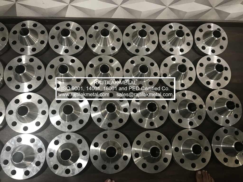
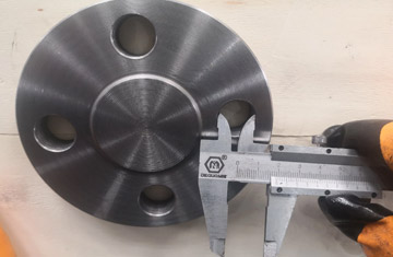
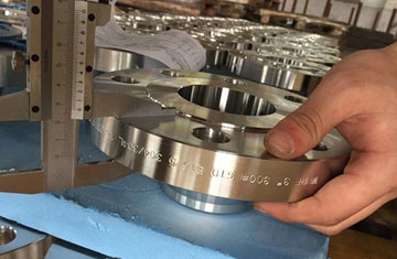
Class 150 forged steel flanges are produced in several configuration styles, including Weld Neck (WN), Slip-On (SO), Blind (BLRF), Socket Weld (SW), Threaded (NPT), and Lap Joint (LJ). Standard facing is a 1/16-inch (1.6 mm) Raised Face (RF) with spiral or concentric serration (125–250 µin AARH). Flat Face (FF) and Ring Type Joint (RTJ) profiles are supplied for specialized high-integrity or non-metallic gasket systems.
What Does Class 150 Mean in Flange Design?
A common misconception is that "Class 150" denotes a maximum operating threshold of 150 psi. In standard engineering practice under ASME B16.5, Class 150 represents a pressure-temperature class designation rather than a static pressure ceiling. For instance, an ASTM A105 carbon steel Class 150 flange withstands a maximum working pressure of 285 psig (19.6 bar) at ambient conditions (-29°C to 38°C). As service temperature increases, allowable working pressure proportionally declines due to temperature-induced material derating.
Technical Manufacturing Specifications
| Parameter | Engineering Compliance Scope |
|---|---|
| Design Standards | ASME B16.5 (1/2″ to 24″), ASME B16.47 Series A/B (26″ to 60″), MSS SP-44 |
| Pressure Classes | Class 150, 300, 400, 600, 900, 1500, 2500 (PN 20 to PN 420) |
| Facing Profiles | Raised Face (RF 1.6 mm), Flat Face (FF), Ring Type Joint (RTJ), Tongue & Groove |
| Surface Finish | Concentric or spiral serrated: 125–250 µin (3.2–6.3 µm) Ra; Smooth finish optional |
| Material Grades | ASTM A105, A350 LF2, A182 F304/304L, F316/316L, F11, F22, F51 (Duplex 2205), Inconel 625 |
| Quality Certifications | EN 10204 Type 3.1 MTC, ISO 9001, NACE MR0175 / ISO 15156, IBR Approved |
ASME B16.5 Class 150 Flange Dimensions in MM & Inches
The table below provides dimensional values for Class 150 flanges ranging from 1/2″ to 24″ Nominal Pipe Size (NPS), including outer diameter, flange thickness, raised face diameter, and length through hub.
| NPS (in) | Flange O.D. (in) | Min. Thickness (in) | RF Diameter (in) | Hub Base Dia. (in) | Length Thru Hub (WN) | Length Thru Hub (SO) |
|---|---|---|---|---|---|---|
| 1/2″ | 3.50 | 0.44 | 1.38 | 1.19 | 1.88 | 0.62 |
| 3/4″ | 3.88 | 0.50 | 1.69 | 1.50 | 2.06 | 0.62 |
| 1″ | 4.25 | 0.56 | 2.00 | 1.94 | 2.19 | 0.69 |
| 1-1/4″ | 4.62 | 0.62 | 2.50 | 2.31 | 2.25 | 0.81 |
| 1-1/2″ | 5.00 | 0.69 | 2.88 | 2.56 | 2.44 | 0.88 |
| 2″ | 6.00 | 0.75 | 3.62 | 3.06 | 2.50 | 1.00 |
| 2-1/2″ | 7.00 | 0.88 | 4.12 | 3.56 | 2.75 | 1.12 |
| 3″ | 7.50 | 0.94 | 5.00 | 4.25 | 2.75 | 1.19 |
| 4″ | 9.00 | 0.94 | 6.19 | 5.31 | 3.00 | 1.31 |
| 6″ | 11.00 | 1.00 | 8.50 | 7.56 | 3.50 | 1.56 |
| 8″ | 13.50 | 1.12 | 10.62 | 9.69 | 4.00 | 1.75 |
| 10″ | 16.00 | 1.19 | 12.75 | 12.00 | 4.00 | 1.94 |
| 12″ | 19.00 | 1.25 | 15.00 | 14.38 | 4.50 | 2.19 |
| 16″ | 23.50 | 1.44 | 18.50 | 18.00 | 5.00 | 2.50 |
| 20″ | 27.50 | 1.69 | 23.00 | 22.00 | 5.69 | 2.88 |
| 24″ | 32.00 | 1.88 | 27.25 | 26.12 | 6.00 | 3.25 |
Class 150 Bolting Pattern & Stud Dimensions
Correct bolt torque and stud selection protect the flange face and gasket from premature joint leakage. The following table specifies bolt quantities, diameters, bolt circle diameters (BCD), and standard stud lengths.
| NPS (in) | No. of Bolts | Bolt Dia. (in) | Hole Dia. (in) | Bolt Circle (BCD in) | Stud Length (RF in) |
|---|---|---|---|---|---|
| 1/2″ | 4 | 0.50 | 0.62 | 2.38 | 2.25 |
| 3/4″ | 4 | 0.50 | 0.62 | 2.75 | 2.50 |
| 1″ | 4 | 0.50 | 0.62 | 3.12 | 2.50 |
| 1-1/2″ | 4 | 0.50 | 0.62 | 3.88 | 2.75 |
| 2″ | 4 | 0.62 | 0.75 | 4.75 | 3.25 |
| 3″ | 4 | 0.62 | 0.75 | 6.00 | 3.50 |
| 4″ | 8 | 0.62 | 0.75 | 7.50 | 3.50 |
| 6″ | 8 | 0.75 | 0.88 | 9.50 | 4.00 |
| 8″ | 8 | 0.75 | 0.88 | 11.75 | 4.25 |
| 10″ | 12 | 0.88 | 1.00 | 14.25 | 4.50 |
| 12″ | 12 | 0.88 | 1.00 | 17.00 | 4.75 |
| 16″ | 16 | 1.00 | 1.12 | 21.25 | 5.25 |
| 20″ | 20 | 1.12 | 1.25 | 25.00 | 6.25 |
| 24″ | 20 | 1.25 | 1.38 | 29.50 | 6.75 |
Class 150 Flange Pressure-Temperature Ratings (Bar & PSI)
Pressure limitations for carbon steel Group 1.1 materials (such as ASTM A105) according to ASME B16.5 Table 2-1.1:
| Temperature (°C) | Temperature (°F) | Working Pressure (Bar) | Working Pressure (psig) |
|---|---|---|---|
| -29 to 38°C | -20 to 100°F | 19.6 bar | 285 psig |
| 50°C | 122°F | 19.2 bar | 278 psig |
| 100°C | 212°F | 17.7 bar | 256 psig |
| 150°C | 302°F | 15.8 bar | 229 psig |
| 200°C | 392°F | 13.8 bar | 200 psig |
| 250°C | 482°F | 12.1 bar | 175 psig |
| 300°C | 572°F | 10.2 bar | 148 psig |
| 350°C | 662°F | 8.4 bar | 122 psig |
| 400°C | 752°F | 6.5 bar | 94 psig |
Class 150 Flange Approximate Weight Chart (KG)
Estimated theoretical weights in kilograms for rapid logistical calculations and shipping weight estimation:
| NPS (in) | Slip On (SORF) | Threaded (NPT) | Socket Weld | Blind (BLRF) | Weld Neck (WNRF) |
|---|---|---|---|---|---|
| 1/2″ | 0.5 kg | 0.5 kg | 0.9 kg | 0.9 kg | 0.9 kg |
| 3/4″ | 0.9 kg | 0.9 kg | 0.9 kg | 0.9 kg | 0.9 kg |
| 1″ | 0.9 kg | 0.9 kg | 0.9 kg | 0.9 kg | 1.4 kg |
| 1-1/2″ | 1.4 kg | 1.4 kg | 1.4 kg | 1.8 kg | 1.8 kg |
| 2″ | 2.3 kg | 2.3 kg | 2.3 kg | 2.3 kg | 2.7 kg |
| 3″ | 4.1 kg | 4.1 kg | 4.1 kg | 4.1 kg | 5.2 kg |
| 4″ | 5.9 kg | 5.9 kg | 5.9 kg | 7.7 kg | 7.5 kg |
| 6″ | 8.6 kg | 8.6 kg | 8.6 kg | 12.2 kg | 11.8 kg |
| 8″ | 13.6 kg | 13.6 kg | 13.6 kg | 21.3 kg | 19.1 kg |
| 10″ | 19.5 kg | 19.5 kg | 19.5 kg | 31.8 kg | 24.5 kg |
| 12″ | 29.0 kg | 29.0 kg | 29.0 kg | 55.8 kg | 39.9 kg |
| 16″ | 48.1 kg | 44.5 kg | 44.5 kg | 81.6 kg | 63.5 kg |
| 20″ | 74.8 kg | 74.8 kg | 74.8 kg | 129.3 kg | 89.4 kg |
| 24″ | 99.8 kg | 99.8 kg | 99.8 kg | 195.0 kg | 121.6 kg |
Procure Verified ASME B16.5 Flanges with EN 10204 3.1 Traceability
Rajtilak Metal provides immediate delivery and custom forging runs for Class 150 to Class 2500 flanges. Connect with our engineering sales desk for complete project schedules and MTC documentation.
Contact Us