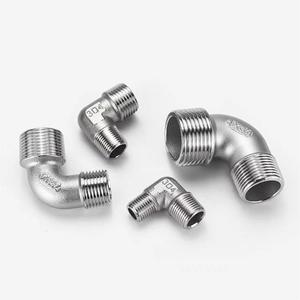
Explore our certified portfolio of ASME/ANSI, DIN, and API forged fittings, flanges, and high-tensile hardware engineered for mission-critical industrial installations.
Combining rigorous metallurgic engineering, integrated forging lines, and multi-national technical certifications to deliver uncompromised joint integrity.
Every lap joint flange and backing ring is laser-engraved or hard-stamped with an individual heat number, linking back to physical and chemical certificates under EN 10204 3.1. Raw materials are verified through PMI spectroscopy prior to heating.
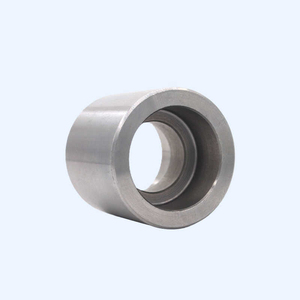
Lap joint bore radiuses require strict adherence to ASME B16.5 and MSS SP-43 tolerances to seat smoothly over matching lap joint stub ends. Our multi-axis CNC lathes machine the inside radius curvature to prevent micro-cracks and stress localization.
Forging carbon steels (ASTM A105, A350 LF2), austenitic stainless steels (ASTM A182 F304/304L, F316/316L, 904L), and exotic duplex alloys. We manufacture composite solutions pairing low-cost carbon backing rings with high-alloy corrosion-resistant stub ends.
A comprehensive examination of loose backing rings, mating mechanics, and technical parameters governing ASME B16.5 and EN 1092-1 Type 02 configurations.
A Lap Joint Flange (LJF), commonly referred to as a loose flange or backing ring, operates in a two-component assembly: the flange ring itself and a lap joint stub end (butt-welded directly to the process pipe). Unlike weld neck or slip-on designs, the lap joint flange is not welded to the pipe. Instead, it slides freely along the pipe length before being brought to bear against the back of the lap joint stub end.
This structural decoupling provides immense mechanical and economic advantages across process facilities that undergo periodic dismantling, frequent inspection, or chemical clean-out operations:
| Standard | Nominal Size (NPS / DN) | Pressure Rating | Flange Facing Style | Governing Stub End Standard |
|---|---|---|---|---|
| ASME B16.5 | 1/2" – 24" | Class 150 to Class 2500 | Flat Face (Backing Stub Shoulder) | ASME B16.9 / MSS SP-43 |
| ASME B16.47 Series A/B | 26" – 60" | Class 75 to Class 900 | Flat Face Machined | ASME B16.9 Butt Weld Specs |
| EN 1092-1 (Type 02) | DN 10 – DN 1200 | PN 6 to PN 100 | Type 32 / 33 Pressed/Forged Collar | EN 1092-1 Type 32 Collars |
| DIN 2642 / 2655 / 2656 | DN 10 – DN 800 | PN 10 to PN 40 | Loose Flange with Smooth Bore Radius | DIN 2641-2642 Welded Collars |
| JIS B2220 | 10A – 600A | 5K to 30K | Loose Plate / Forged Hub | JIS Butt-Weld Fitting Series |
The inside radius where the bore meets the front seating face is a critical manufacturing dimension. According to ASME B16.5, this corner radius (R) must correspond accurately to the radius of the mating stub end's fillet. If a manufacturer leaves the radius too sharp, the flange will not seat flush against the stub end shoulder, setting up high bending moments across the bolt circle. Conversely, excessive radius will diminish the bearing area, causing local yield when tightening bolts to target torque values.
Strategic structural shifts and material engineering advances changing how global EPCs and plant operators source lap joint configurations.
Global operators are abandoning paper test reports. Advanced manufacturers in China are adopting cloud-linked QR-code laser etching directly onto flange outer diameters, allowing field inspectors instant access to heat chemical analysis, Charpy V-notch impact values, and ultrasonic test certs.
Procurement teams are moving away from whole-line exotic solid alloy flanges. By deploying carbon steel lap joint backing rings (often hot-dip galvanized or epoxy coated) over Super Duplex 2507 or 904L stub ends, overall CAPEX decreases by 40% to 65% on high-grade chemical processes without impacting line pressure ratings.
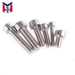
With volatile maritime logistics, tier-one international buyers favor manufacturers with integrated forging hammer capacities capable of rapid turnaround for non-standard wall thicknesses (SCH 160, SCH XXS) and quick delivery of both metric and UNC fasteners in matched kits.
Our technical team reviews drawings, material balance sheets, and custom bore requirements within 24 hours.
Inquire NowPractical answers to technical dilemmas encountered by mechanical engineers, procurement agents, and QA/QC teams.